Current Regulative Diodes Q&A

Q1.Q1. Is it possible to increase the current value by connecting CRDs in parallel?

A1.

A1. Each CRD can be considered as a current source, so it is possible to connect current sources in parallel

When connected in parallel, the current flowing through the same or different current value combinations is the sum of the current values.


Figure 1. Example of parallel connection of CRDs (1)

There is also no limit to the number of CRDs that can be connected in parallel. For example, if five 18mA products are connected in parallel, a large current of 90mA can be produced. Other combinations of parallel connections can be used in various circuit configurations.


Figure 2. Example of parallel connection of CRDs (2)

Q2.Q2. Is it possible to increase the maximum working voltage value by connecting CRDs in series?

A2.

A2. Series connection is possible by protecting the CRDs from overvoltage.

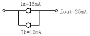
CSince each CRD can be considered as a current source, series connection of current sources is generally prohibited, but the following method enables the use of series connections.

If CRDs are simply connected in series, the voltage will be concentrated on the side with the lowest current value, resulting in the problem of the maximum working voltage being exceeded.

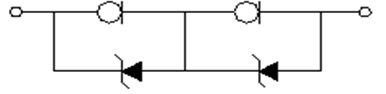
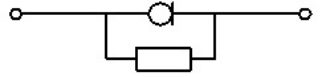
Therefore, it is necessary to devise a way to ensure that the maximum working voltage of the CRD is not exceeded. As shown in the figure below, a zener diode is connected in parallel with the CRD to protect the CRD from overvoltage. At this time, a product with the same current value should be selected for the CRD.


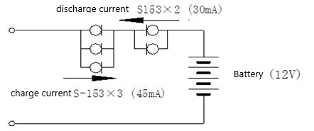
Figure 3. Example of series connection

For the zener diode to be connected, one should be selected whose breakdown voltage does not exceed the maximum working voltage of the CRD. Table 1 shows a correspondence table.

Table 1: Correspondence table for zener diodes when CRDs are connected in series
Characteristics E series S series
Maximum working voltage Zener voltage Maximum working voltage Zener voltage
101~562 100 91 100 91
822 30 27 50 47
103 30 27 50 47
123 30 27 50 47
153 25 22 50 47
183 25 22 40 36

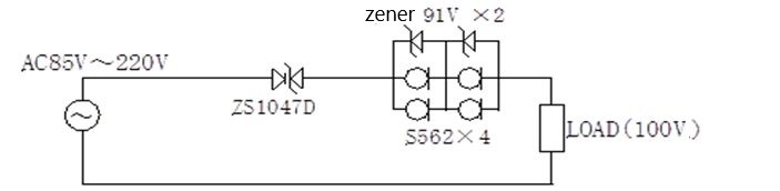
Figure 4. Example of series connection circuit

By connecting CRDs in series, it is possible to supply constant current to the load over a wide voltage range of 85 VAC to 220 VAC. However, this circuit is not an efficient circuit because the CRD bears most of the voltage. Therefore, it is an effective circuit when the current is small.

Q3.Q3. Is it possible to create a bidirectional constant current by connecting CRDs in series?

A3.

A3. Bidirectional constant current characteristic can be achieved by connecting the cathodes of the CRDs in series opposite each other.

It can be applied to cases where a bidirectional constant current characteristic is required, current limiting in case of reverse current flow in the event of trouble, etc.


Figure 5. Example of bidirectional connection of CRDs (1)

It is also possible to set the current value to unbalanced as shown in the figure below.


Figure 6. Example of bidirectional connection of CRDs (2)

For example, in a battery charge current and discharge current limiting circuit, the charge current and discharge current can be set separately by changing the number of parallel connections.

Q4.Q4. CRD has two characteristics, dynamic and static. What is the difference between the two characteristics?

A4.

A4. Static characteristic is the current-voltage characteristic of the CRD measured by pulse (pulse width: 20 ms), and dynamic characteristic is that measured when the CRD is continuously energized with direct current.
With a dynamic characteristic, the current value tends to decrease as the applied voltage increases due to self-heating.

As shown in the figure below, the static characteristic results in a constant current value even if the applied voltage changes from 10 V onward. Characteristics measured with short pulse times are values measured under conditions where heat generation due to energization is negligible.

Graph 1. CRD S series static characteristic

The dynamic characteristic is the current-voltage characteristic when continuously energized with direct current.
This is the characteristic of the current value when the CRD is self-heated and thermally saturated by energizing.

Compared to the static characteristic, the dynamic characteristic tends to lower the current as the applied voltage increases. The power P = V × I due to the voltage V and current I applied to the CRD results in heat. If the amount of heat generated is small enough compared to the thermal resistance of the CRD, there will not be a noticeable temperature increase. However, when CRDs are used with a power of 100 mW or more, the effect of the temperature increase due to self-heating cannot be ignored.

This tendency is more pronounced for CRDs with larger currents.
In contrast, low-current products have a good constant-current characteristic with no self-heating effect.

Graph 2. CRD S series dynamic characteristic

Q5.Q5. Is there any way to improve the constant current characteristic of the CRD’s dynamic characteristic?

A5.

A5. The constant current characteristic can be improved by connecting a self-heating compensating resistor in parallel.

The dynamic characteristic of the CRD is that the current value decreases as the applied voltage increases due to self-heating, but this current decrease can be compensated by connecting a resistor in parallel to the CRD.


Figure 7. Parallel connection of self-heating compensating resistors

Table 2 shows the compensating resistance of the CRD S and E series.

(1) S series (500mW)
Type name S-102 S-152 S-202 S-272 S-352 S-452 S-562 S-822 S-103 S-123 S-153 S-183
Resistance value 1.1MΩ 430kΩ 300kΩ 200kΩ 130kΩ 91kΩ 62kΩ 27kΩ 18kΩ 15kΩ 12kΩ 9.1kΩ

(2) E series (300mW)
Type name E-102 E-152 E-202 E-272 E-352 E-452 E-562 E-822 E-103 E-123 E-153 E-183
Resistance value 1MΩ 390kΩ 240kΩ 120kΩ 82kΩ 56kΩ 39kΩ 20kΩ 15kΩ 11kΩ 9.1kΩ 7.5kΩ

Current regulative diodes with a pinch-off current of 1 mA or more have a negative temperature coefficient of current, and their current value decreases due to self-heating.

A good constant-current characteristic can be achieved by limiting the decrease in current value with a compensating resistor.

Graph 3 and Graph 4 show the dynamic characteristic after compensation with self-heating compensation resistance.

Since the selection of the optimal self-heating compensating resistance depends on the thermal resistance of the mounting condition, it is recommended to determine this optimal resistance by experimentation by changing the resistance value in the actual mounting condition.

Graph 3. CRD S series dynamic characteristic after compensation


Graph 4. CRD E series dynamic characteristic after compensation


single