1. Circuit conditions for using power thermistors
The selection will be made using the following conditions
Ta max :Maximum ambient temperature of the circuit: ______℃
IL : Load current of the circuit: ______A
(Value of current flowing through power thermistor)
VAC rms :Maximum power supply voltage: ______V
IP :Allowable inrush current: ______A
CX :Smoothing capacitance: ______μF
2. How to select a power thermistor
– Resistance value selection
Condition (1): Find the resistance value RX when converted to 25℃
VP :Peak value of VAC rms= VAC rms × √2 =____V
RTm :Resistance value at Ta max ____Ω
(*Refer to Table 1 [Resistance Temperature Characteristics] for resistance values.)
Calculate the resistance value RX converting RTm
RX = 1/RTm × (VP/IP) =____Ω
Select a power thermistor with nominal zero load resistance value R25≧RX
– Selection of shape
Condition (2): Find the current value IX when converted to 25℃
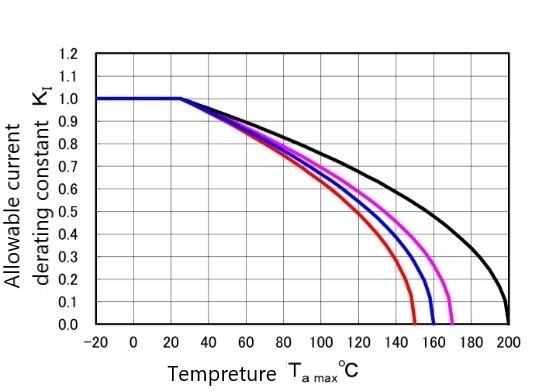
KI :Allowable current derating factor at temperature Ta max ____
(*Please refer to Graph 1 for allowable current derating factors for each temperature)
Calculate the current value IX when converted to 25℃
IX = IL / KI =____A
Select a power thermistor with maximum current I≧IX
Condition (3) Find the capacitance of capacitor CX AC100V when converted to AC100V
CX AC100V:Capacitance of capacitor converted from CX to AC 100V
CX AC100V = CX × (VAC rms × √2)2 / (100 × √2)2 =____μF
Select a power thermistor with allowable capacitance of capacitor C≧CX AC100V at AC100V
Select a power thermistor that satisfies all conditions [(1), (2), and (3)] from the characteristics rating table in our power thermistor catalog.
This selection method is applied using typical values of electrical characteristics.
When actually using a power thermistor, please evaluate and verify with the actual device before use.
Table 1 Resistance temperature characteristics table
Graph 1 Allowable current derating curve
The curve varies depending on the operating temperature range of the power thermistor.
For initial selection, read the allowable current derating factor from the red line and make the selection.